
What does the ATC CyberCabinet software do?
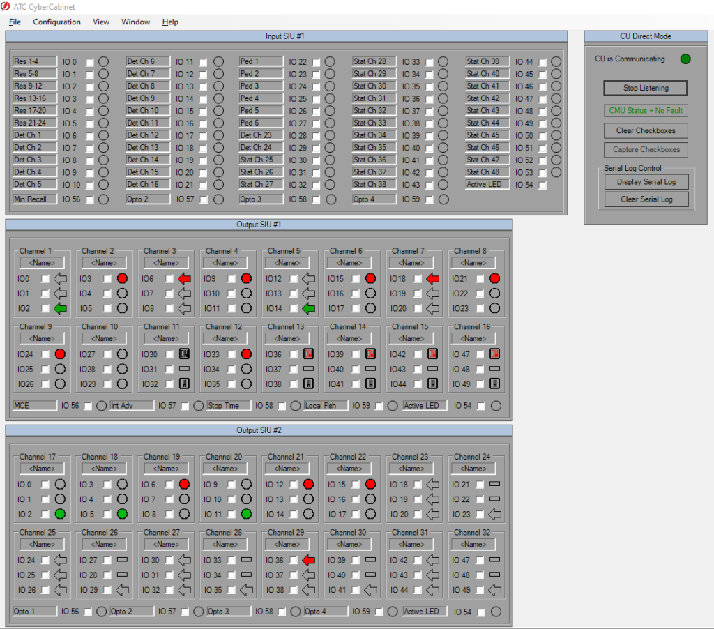
The ATC CyberCabinet software emulates the functionality of the standard Input & Output Serial Interface Units (SIU / BIU / FIO) of the cabinet, along with the Cabinet Monitor Unit (CMU / MMU2 / 2018KCL), eliminating the need for a fully configured Cabinet Assembly.
- ATC Cabinet Mode
- Seven SIUs are provided
- Two Output SIUs for 32 channels of signal outputs
- Five Input SIUs for 120 channels of detection
- Seven SIUs are provided
-
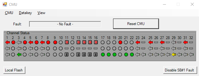
- A 32 channel Cabinet Monitor Unit (CMU2212) function is provided
- Configured with the parameters from an actual intersection Datakey
- Broad fault coverage to confirm Controller database compatibility.
- A 32 channel Cabinet Monitor Unit (CMU2212) function is provided
- NEMA TS-2 Cabinet Mode
- Eight BIUs are provided
- Four Terminals & Facilities BIUs for 16 channels of signal outputs
- Four Input BIUs for 64 channels of detection
- Eight BIUs are provided
-
- A 16 channel Malfunction Management Unit (MMU2) function is provided
- Broad fault coverage including NEMA standard FYA modes to confirm Controller database compatibility.
- A 16 channel Malfunction Management Unit (MMU2) function is provided
- TEES 33x Cabinet Mode
- The 2070 Field IO Module is provided
- 53 Inputs for control and detection
- 53 outputs for 18 channels of signal outputs with Aux File.
- The 2070 Field IO Module is provided
-
- A 18 channel Cabinet Monitor Unit (2018KCL) function is provided
- Configured with the parameters from an actual intersection Datakey
- Broad fault coverage to confirm Controller database compatibility.
- A 18 channel Cabinet Monitor Unit (2018KCL) function is provided
- ITS Cabinet Mode
- Seven SIUs are provided
- Two Output SIUs for 32 channels of signal outputs
- Five Input SIUs for 120 channels of detection
- Seven SIUs are provided
-
- A 32 channel Cabinet Monitor Unit (CMU212) function is provided
- Configured with the parameters from an actual intersection Datakey
- Broad fault coverage to confirm Controller database compatibility.
- A 32 channel Cabinet Monitor Unit (CMU212) function is provided
The CU Direct mode responds to SB#1 (Port1) HDLC commands from the target Controller using the ATC CyberCabinet HDLC Interface Module.
No other hardware is needed.

Beacons,
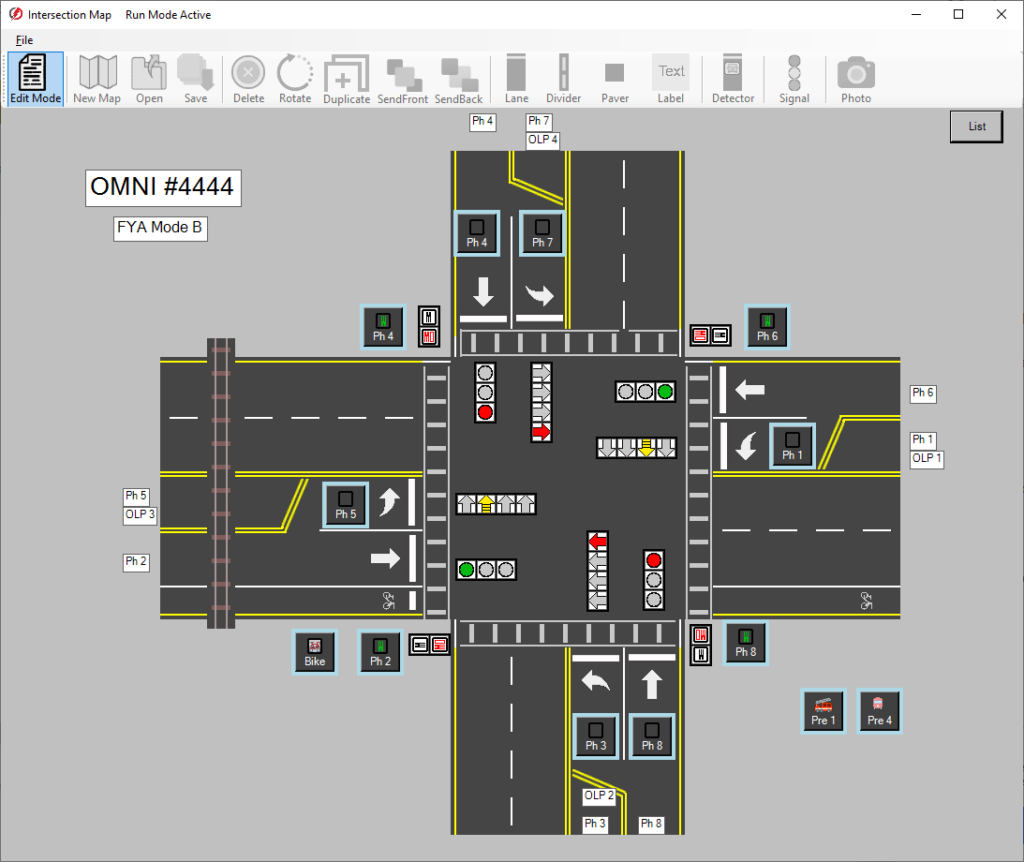
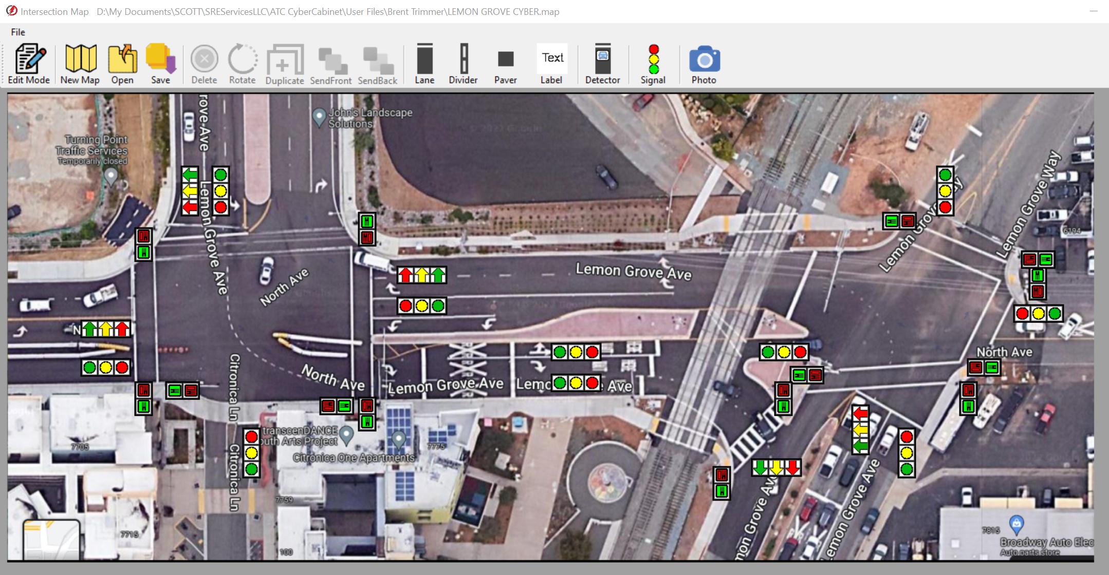
To generate Detector inputs and visualize and validate Signal outputs, a Map editor is provided to generate an icon based version of the intersection. Active icons are used in the Map View mode for Detector inputs, Ped buttons, Preempt, Beacons, and configurable Signal Heads.
This is a screen shot of the Map View mode showing an 8-phase FYA quad design and a 22 channel dual intersection design using a photo background
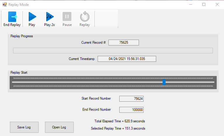
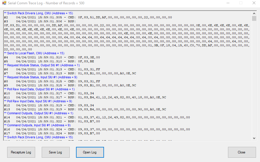
A SB#1 (Port1) Trace Log recording function (sniffer) is provided to inspect Controller command frame sequencing and replay Controller movements.
Did a preemption sequence not operate correctly?
Replay and review what the Controller actually did.
- Capture and Replay an interval of Controller steps.
- Trace Log capture is Manually triggered or triggered by a CMU / MMU fault.
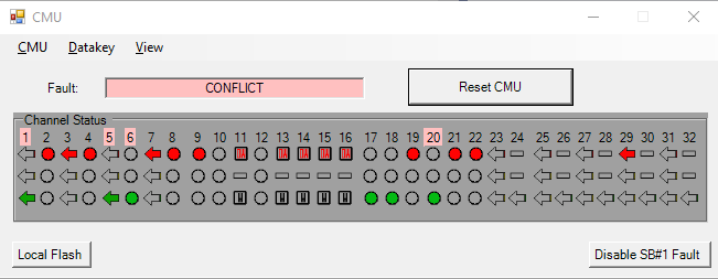
In ATC mode a32 Channel Cabinet Monitor Unit (CMU2212) function is provided.
- Test and Validate the CMU configuration using the exact Datakey configuration for the target cabinet during Controller test and evaluation.
- Test Preemption Sequences and complex movements for CMU compatibility.
- Datakey parameters can be read from a Key file on disk, or directly from the EDI MonitorKey® Programmer.
Eliminate surprises when the physical cabinet is installed on the street.
Future-Proof Your ATC Controller Development and Test Program
ATC CyberCabinet Software
Contact SRE Services or your preferred ATC Cabinet supplier for more information.
